Basic Electronics for Artists:
Components:
Resistors
Capacitors
LEDs
Switches
Potentiometers
Relays
Transistors
Thru hole/SMT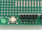 
|
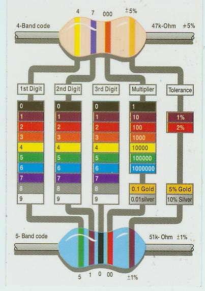
Resistor Color Codes:
 |
AC/DC, Voltage, Current, Resistance
- V=Voltage, a measure of electrical force, electrical potential, Volts V
- I=Current, the rate of flow of electricity, think of water in a pipe, Amps A
- R=Resistance, resist the flow of electricity, Ohms Ω
Ohm's Law
Kirchoff's Voltage Law
- In any circuit the total voltage around the path is zero. If a battery provides 9V then the components in the circuit must consume 9V.
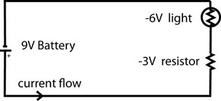 9V -6V -3V = 0V
- In this scenario, we need the resistor to consume 3V of power to prevent the light from burning out. In order to determine the value of the resistor, we can use Ohm's Law, V=IR. However, we need to know one more thing about the light, it's current draw. Let's say that this light draws 20mA of current at 6V.
- We can now solve our equation for the resistor, but realize that the value for V is 3V, because that's how much voltage we want the resistor to consume.
- SO, V=IR, or 3=.02(R) remember you must have each value in Volts, Amps, and Ohms, not milliVolts, milliAmps, or milliOhms....right?
- SO, 3/.02=150Ω and this is the value of the resistor that will work in this circuit.
Series circuits (voltage adds, current is continuous)
A series circuit is a circuit in which resistors are arranged in a chain, so the current has only one path to take. The current is the same through each resistor. The total resistance of the circuit is found by simply adding up the resistance values of the individual resistors:
equivalent resistance of resistors in series : R = R1 + R2 + R3 + ...

A series circuit is shown in the diagram above. The current flows through each resistor in turn. If the values of the three resistors are:

With a 10 V battery, by V = I R the total current in the circuit is:
I = V / R = 10 / 20 = 0.5 A. The current through each resistor would be 0.5 A.
Parallel circuits( current adds, voltage is continuous)
A parallel circuit is a circuit in which the resistors are arranged with their heads connected together, and their tails connected together. The current in a parallel circuit breaks up, with some flowing along each parallel branch and re-combining when the branches meet again. The voltage across each resistor in parallel is the same.
The total resistance of a set of resistors in parallel is found by adding up the reciprocals of the resistance values, and then taking the reciprocal of the total:
equivalent resistance of resistors in parallel: 1 / R = 1 / R1 + 1 / R2 + 1 / R3 +...
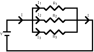
A parallel circuit is shown in the diagram above. In this case the current supplied by the battery splits up, and the amount going through each resistor depends on the resistance. If the values of the three resistors are:

With a 10 V battery, by V = I R the total current in the circuit is:
I = V / R = 10 / 2 = 5 A.
The individual currents can also be found using I = V / R. The voltage across each resistor is 10 V, so:
I1 = 10 / 8 = 1.25 A
I2 = 10 / 8 = 1.25 A
I3=10 / 4 = 2.5 A
Note that the currents add together to 5A, the total current.
Power
- W=VI or W=Iˆ2*R
- Batteries are rated in AH amp-hours or mAH.. which means that the battery can supply its stated voltage for one hour at a certain amperage(rate)
- Power supplies, sometimes called wall warts, or AC to DC transformers, will have a voltage rating and a current rating. The voltage rating of the supply needs to be precisely what your circuit requires. The current rating needs to be at least 30% more than your peak current draw. If this current rating is lower than what your circuit draws, you will burn up the supply.
- There are many types of batteries: Alkaline, Ni-Cad, Lead Acid, SLA, Li-ion, Li-polymer
Voltage Dividers
- A series or parallel circuit using resistors to divide voltage into known quantities. A simple example is a series circuit with two resistors:
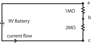
- The voltage across a to c is 9V, the voltage across a to b is 3V, and the voltage across b to c is 6V.
- The resistors here are 1MΩ and 2MΩ which means they are very high resistances, which limits the amount of current and limits any unnecessary power consumption, in this case 3 micro-Amps or 3x10ˆ-6.


 9V -6V -3V = 0V
